Shell and tube heat exchanger in their various construction are probably the most widespread and commonly used basic heat exchanger configuration in the process industries. The reasons for this general acceptance are several. The shell and tube heat exchanger provides a comparatively large ratio of heat transfer area to volume and weight. It provides this surface in a form which is relatively easy to construct in a wide range of sizes and which is mechanically rugged enough to withstand normal shop fabrication stresses, shipping and field erection stresses, and normal operation conditions. There are many modifications of the basic configuration, which can be used to solve special problems. The shell and tube heat exchanger can reasonably easily clean, and those components most subjects to failure gasket and tubes can be easily replaced. Finally, good design method exists, and the expertise and shop facilities for the successful design and construction of shell and tube heat exchanger are available. Different no. of passes can also be given depending on the size and requirement of the Heat exchanger.
Heat Exchanger
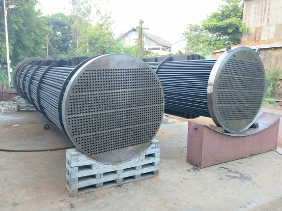
1. Shell & Tube Heat Exchanger
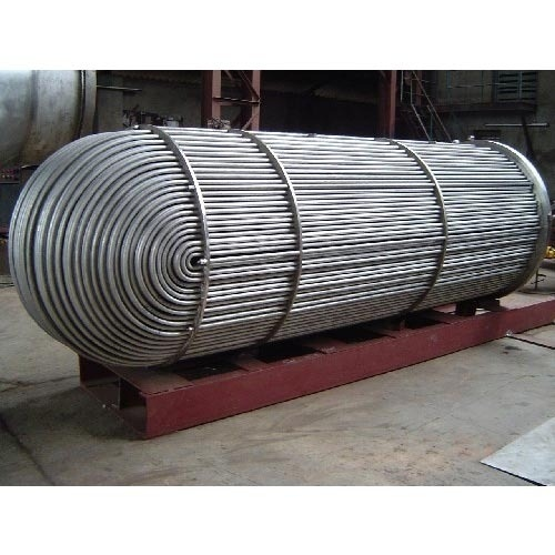
2. U-Tube Heat Exchanger
The U-tube head (U) is a very simple design requiring a bundle of U tubes, only one tube sheet, no expansion joints, and no rear-end head at all, allowing easy removal of the bundle. The thermal stress problem is eliminated because each tube is free to expand/contract independently. One disadvantage is, individual tube replacement is not possible except in the outer rows, and an even number of tube passes is required. Some tubes are lost in the center due to HEAT EXCHANGERS 17.7 tube bend limit, and tube side mechanical cleaning of the bends is difficult. Flow-induced vibration could be a problem for tubes in the outermost row. It is the lowest-cost design because there is no need for the second tube sheet.